In the realm of modern architectural design, the selection of surface drainage systems has evolved from a mere infrastructural consideration into a complex interplay of architectural aesthetics, safety performance, and operational efficiency.
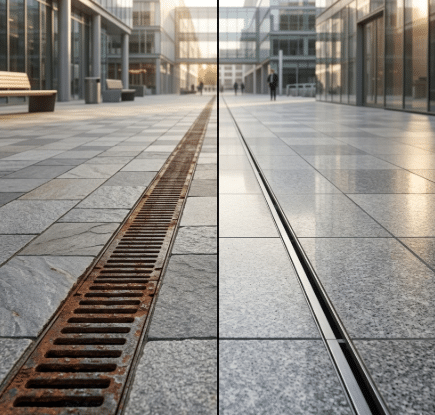
For a long time, traditional trench drain systems—characterized by their grated covers—have remained the mainstream choice for industrial and commercial buildings; however, their visually disruptive nature, maintenance complexities, and potential hygiene risks have prompted designers to seek out more advanced alternatives.
The slot drain system, an innovative linear drainage solution, is rapidly emerging as the preferred choice among contemporary architects, distinguished by its minimalist aesthetic, exceptional durability, and strict adherence to the highest hygiene standards.
The Historical Evolution and Modern Trends of Surface Drainage Design
Throughout the history of architecture, drainage design has undergone a significant transformation, evolving from point drainage to linear drainage. Early point drainage systems relied on multiple circular or square inlets, necessitating complex four-way grading of the ground surface to direct water toward these specific drainage points. This multi-directional sloping not only increased construction difficulty and costs but also frequently resulted in uneven ground surfaces—conditions that were highly unfriendly to wheelchair users and wheeled equipment.
The advent of linear drainage systems has completely revolutionized this status quo. Their linear design facilitates simple, single-direction grading of the ground surface, thereby vastly simplifying the geometric logic of paving layouts. Within the realm of linear drainage, while grated systems are capable of handling substantial surface runoff, their exposed, wide grates appear visually obtrusive and are prone to deformation, corrosion, or damage over time. In contrast—and patented in its modern form in 1988—the slot drainage system eliminates bulky grate covers in favor of an extremely narrow surface opening, concealing the expansive drainage channel beneath the ground. This “invisible” quality enables architects to fully preserve the visual continuity of premium stone, tile, or polished concrete finishes, achieving a perfect balance between functionality and aesthetics.
Comparison of Basic Structures of Linear Drainage Systems
| System Features | Traditional Grate Drainage System | Modern Slot Drainage System |
| Visual Visibility | High; the grille cover detracts from the aesthetic appeal of the paving. | Extremely low; a gap of only about 1.3 centimeters in width. |
| Slope Design | Simple unidirectional slope. | Simple unidirectional slope. |
| Component Structure | Drainage Channel Body + Split Grate Cover | Integrated precast channel body, without cover plates. |
| Ground Integrity | The opening in the floor is relatively large, resulting in a significant weakening of the structure. | The opening is extremely narrow, and the structural integration is highly advanced. |
| Customization Flexibility | Limited by standard grille dimensions. | High; customizable arc-shaped and special-angle elbows available. |
Key Technical Parameters of Slotted Drainage Systems
The design essence of a slot drainage system lies in its “funnel-shaped” internal cross-section. The narrow surface slot connects to a larger stainless steel drainage channel situated beneath; this design leverages the principles of gravitational acceleration and fluid dynamics to ensure that water, once it enters the slot, converges and drains rapidly. The width of the slot serves as a critical parameter in determining the system’s hydraulic efficiency and safety rating.
Currently, standard industry slot widths typically range from 0.5 inches (approximately 1.27 cm) to 1.25 inches (approximately 3.18 cm). The 0.5-inch model is the ideal choice for pedestrian areas, as it fully complies with Americans with Disabilities Act (ADA) standards and effectively prevents women’s high heels from becoming lodged in the grate. In settings such as industrial facilities or heavy-duty car washes, wider slots are selected to accommodate higher-intensity, instantaneous drainage requirements.
Reference Table: Relationship Between Slot Width and Drainage Flow Rate
The drainage flow rate of a slot drainage system is determined jointly by the opening width and the channel depth.
| Gap Width (inches) | Drainage Rate (Gallons/Minute/Foot) | Typical Application Scenarios |
| 0.5″ (ADA standard) | 11 GPM | Public squares, hotel lobbies, sidewalks. |
| 1.0″ | 18 GPM | Commercial Kitchens, General Industrial Workshops |
| 1.25″ | 27 GPM | High-Intensity Food Processing Zones, Heavy-Duty Vehicle Wash Bays. |
Data indicates that a section of 1.25-inch slot drain, approximately 3 meters in length, can discharge about 260 gallons of liquid per minute. This highly efficient drainage capacity is sufficient to drain a standard Olympic-sized swimming pool within just 42 hours, demonstrating its reliability in extreme weather conditions or high-flow flushing environments.
Architectural Integration and Aesthetic Expression
In contemporary architecture—characterized by its pursuit of minimalism and a high-tech aesthetic—the visual presence of drainage channels is often perceived as “design noise.” Traditional cast iron or plastic grates, regardless of how they are finished, inevitably leave conspicuous black lines or contrasting streaks across the floor surface. For projects with exacting visual standards—such as museums, art centers, and luxury hotels—slot drainage systems offer a nearly perfect solution.
Slot drainage systems can be seamlessly integrated with architectural materials. For instance, when installing tiles or paving stones, designers can position the drainage slot directly within the joints, allowing it to blend harmoniously with the grout lines. Furthermore, the stainless steel surfaces and edges can be finished with either a brushed or mirror polish, adding a touch of refined industrial aesthetic to the flooring.
The geometric flexibility of slot drain systems constitutes another major advantage. Through precision bending techniques, these systems can be engineered to feature curved designs with specific radii—known as Radius Slot Drains—thereby seamlessly conforming to the contours of fountain edges or winding garden paths. Such streamlined designs are virtually unattainable with traditional grate-based drainage systems; the latter require complex mitered splicing to accommodate curves—a process that not only compromises aesthetic appeal but also creates structural weak points.
Hygienic Performance, Infection Control Requirements, and Food Safety Compliance
In hygiene-critical sectors—such as food and beverage processing and pharmaceuticals—the design of drainage systems directly impacts production safety and regulatory compliance. According to data from the U.S. Department of Agriculture (USDA), approximately 40% of Listeria contamination sources in meat processing plants originate from floor drains.
Traditional grate drainage systems possess inherent disadvantages in terms of hygiene:
- Grille Dead Zones: The mesh structure and interlocking slots of the grille serve as breeding grounds for bacteria; these tiny crevices are extremely difficult to thoroughly clean and disinfect.
- Splash Contamination: When high-flow liquids strike the grate cover, aerosolized splashes are generated, dispersing pathogenic bacteria from within the piping onto production equipment or product surfaces.
- Right-Angle Accumulation: Traditional flat-bottomed drainage channels often feature right angles, which tend to facilitate the accumulation of organic matter and the proliferation of anaerobic bacteria, resulting in foul odors.
Slot drainage systems address these pain points through dual innovations in both materials and structure. Typically fabricated from food-grade 304 or 316 stainless steel, the system features a smooth, non-porous surface capable of withstanding highly alkaline cleaning agents and high-temperature rinsing. Crucially, the base of modern slot drains employs a curved—or radius-edge—design, which eliminates all physical dead zones for cleaning and ensures that the flow of water generates a self-cleaning effect.
Daily Maintenance Labor Cost Comparison (Based on 100 Feet of Drain Pipe)
The physical labor and time costs associated with removing grates for cleaning constitute a heavy burden on operations.
| Maintenance Phase | Traditional Grate Drainage System | Slot Drainage System |
| Sedimentation Tank Cleaning | 3–5 minute | 3–5 minute |
| Cover Removal and Cleaning | 120–210 minute | / |
| Internal Tank Scrubbing | 60–90 minute | 20–25 minute |
| Automatic flushing duration | / | 1–2 minute |
| Total Daily Time Spent | 2–5 Hour | 24–32 minute |
| 年度劳动力成本 | $9,516 – $15,860 | $1,248 – $1,664 |
By incorporating Clean-in-Place (CIP) and Flush Flo automatic flushing technologies, the cleaning efficiency of slit-type systems can be boosted by approximately 90%. This not only results in substantial savings on labor costs but also significantly mitigates food safety risks stemming from incomplete manual cleaning.
Structural Toughness and Load Class Standards
Architects often express concern regarding whether extremely narrow slots possess sufficient load-bearing capacity. In reality, the slot edges of slot drainage systems are typically reinforced with stainless steel angle bars and deeply anchored into the underlying concrete base, thereby forming an exceptionally robust composite structure. When assessing system strength, the industry commonly references the European standard EN 1433 and the American standard ASME A112.6.3.
Drainage Load Classes and Their Application Environments
| Load Class (EN 1433) | Static Test Pressure (lbs) | Typical Application Environment |
| Class A | 3,372 lbs | Restricted to pedestrians and bicycles (e.g., private gardens). |
| Class B | 28,100 lbs | Private Car Garage, Light-Duty Pedestrian Walkway. |
| Class C | 56,200 lbs | Commercial Parking Lots, Shopping Center Delivery Zones |
| Class D | 89,923 lbs | Public Roads and Highway Emergency Lanes |
| Class E | 134,885 lbs | Industrial workshops and warehouses with frequent forklift traffic. |
| Class F | 202,328 lbs | Airport runways, military piers, container ports. |
Even under heavy load classes (such as Class E/F), slot drainage systems retain their slender visual profile. This is because the load is primarily transferred from the channel walls to the underlying concrete support structure, rather than being borne independently by the surface cover plate. This distributed load-bearing mechanism effectively prevents the cracking or dislodgment issues often encountered with traditional grates due to uneven load distribution.
Life Cycle Cost Analysis: The Trade-off Between CAPEX and OPEX
In project decision-making, initial procurement costs (CAPEX) often take center stage; however, for buildings intended for long-term operation, operating expenses (OPEX) are the core factor influencing financial performance.
Initial Installation Cost (CAPEX)
Market data from 2025 indicates that the installation cost for standard drainage ditches ranges from $120 to $800 per linear foot, depending on material strength.
- High-Density Polyethylene (HDPE) Systems: Approximately $45–$95 per foot (materials only). Although inexpensive, they offer limited heat and chemical resistance.
- Stainless Steel Tank: Approximately $150–$320 per linear foot (materials only).
- Grating Covers: High-quality grating (such as stainless steel or ductile iron) entails an additional cost of $90–$220 per linear foot.
Operating Expenses and Depreciation (OPEX)
Although slot drainage systems entail a higher initial investment, they demonstrate exceptional cost-effectiveness over their operational lifecycle. Traditional grate covers typically require replacement every 5 to 10 years when exposed to heavy loads or chemically corrosive environments. Moreover, the potential liability risks associated with slip-and-fall accidents—stemming from lost or damaged grates—constitute an incalculable financial hazard.
Based on a 40-year whole-life cycle estimate, the total cost of ownership for slot drainage systems is typically more than 40% lower than that of grate systems, largely because they require virtually no cover replacement and offer a 90% reduction in daily manual cleaning labor.
Materials Science: Performance Differences Between 304 and 316 Stainless Steel
When specifying a drainage system, the selection of the alloy grade determines the system’s ultimate service life. Stainless steel remains “stainless” because an extremely dense passivation film forms on its surface.
304 vs. 316 Grade Comparison
| Material Grade | chemical composition | Key Features | Applicable Environment |
| 304 Stainless Steel | 18% Chromium, 8% Nickel | It offers excellent overall performance and high cost-effectiveness. | Indoor public areas, general commercial kitchens. |
| 316 Stainless Steel | 18% Chromium, 10% Nickel, 2% Molybdenum | Exceptional pitting resistance and resistance to chloride ions. | Coastal areas, chemical plants, high-salinity environments. |
In environments containing high concentrations of salts (such as sidewalks treated with road salt in winter) or chlorides (such as saltwater pools), 316 stainless steel is the only material that meets professional standards. The addition of molybdenum effectively prevents pitting corrosion—caused by the localized breakdown of the passive film—thereby ensuring that the system maintains a structural service life of over 40 years, even under extreme conditions.
Building Information Modeling (BIM) and Construction Integration
Modern construction workflows demand a high degree of design collaboration. Manufacturers of slot drainage systems now provide comprehensive BIM object libraries that support mainstream software such as Revit, AutoCAD, and ArchiCAD. By simulating water flow paths and potential conflicts with underground utility networks within a virtual model in advance, architects can significantly reduce the number of on-site change orders.
Summary of On-Site Construction Procedures
- Site Preparation: The excavation depth must ensure a minimum concrete encasement of 6 inches (15 cm) surrounding the tank body to maintain the structural integrity of the load-bearing system.
- Tank Body Connection: The system consists of pre-fabricated tank segments; these segments are fastened together using bolts, and a specialized silicone sealant must be applied at the joints to prevent leakage.
- Leveling and Fixing: The pre-installed adjustable brackets allow for extremely precise elevation adjustments prior to concrete pouring.
- Concrete Pouring and Finished Product Protection: During the pouring process, joint openings must be sealed using specialized tape or foam strips; under no circumstances is cement mortar permitted to enter the channel body.
- Activation and Finishing: Once the ground has hardened, remove the protective tape and knock away the metal support ribs; the system is then ready for use.
The choice modern architects make between slot drainage systems and traditional grate systems reflects a profound shift—moving from merely “solving drainage problems” to “optimizing user experience and operational value.” Although slot systems entail a relatively higher initial investment in materials, their superior aesthetic integration, stability under extreme loads, cleaning efficiency in meeting rigorous hygiene standards, and virtually maintenance-free longevity give them a decisive advantage in Life Cycle Cost (LCC) analyses.
In today’s era, where minimalist aesthetics prevail, slot drainage systems serve as far more than mere functional components; they are integral elements of architectural art. By concealing complex engineering mechanisms beneath the surface while reserving clean, simple lines for the ground level, they achieve a profound synthesis of structural aesthetics and pragmatism. As standards for sustainable architecture and accessibility regulations become increasingly rigorous, linear slot drainage is poised to become the standard solution for high-quality architectural projects.
Frequently Asked Questions (FAQ)
1. Can a slot drainage system withstand repeated heavy vehicle traffic?
Absolutely. Slot drainage systems specifically designed for heavy-duty applications can achieve Class F classification under the EN 1433 standard by incorporating increased wall thickness and internal reinforcement. This means they are capable of withstanding loads exceeding 200,000 pounds, making them suitable for use in airport aprons, fire station entrances, and heavy-duty logistics centers.
2. What happens if such a narrow gap gets clogged with leaves or debris?
This is a common misconception. In reality, the inlets of a slot drainage system—characterized by their narrow openings—serve as a primary physical barrier, effectively preventing large debris from entering the channel body. As for smaller particles that do enter the slot, the system utilizes a pre-engineered gradient and smooth stainless steel surfaces to generate high-velocity flushing forces, thereby conveying these particles downstream into a sedimentation tank. Furthermore, the Flush Flo automatic flushing system enables maintenance personnel to easily clear any accumulated silt from the interior.
3. Does the installation of slot drains impose strict requirements on the ground slope?
Since the system typically incorporates a built-in internal slope of 0.5% or 1%, the requirements for grading the construction site floor are significantly reduced. Even on a flat floor slab, provided the system elevation is correctly established, the internal physical slope ensures that water continuously flows toward the outlet.
4. Is a slot drainage system truly more cost-effective than grate drainage in food processing environments?
Yes, the savings are truly remarkable. Based on field data collected from a 100-foot drainage line, the annual labor cost for cleaning a slot drainage system is only around $1,500; in contrast, a grate-based system—which requires frequent removal and cleaning—often incurs average annual labor costs exceeding $10,000. This 90% reduction in labor typically allows the system to recoup its premium cost within just two to three years of operation.